5. Modeling for product design
Product design is originally a commercial term, but in the 3D world, it often means modeling something with the idea to have it 3D-printed or, more generally, manufactured by a machine, for example a 3D printer or a CNC machine.
When you print objects in 3D, it is of ultimate importance that your objects are solid. As they will become real, solid objects, this is obvious. Nothing prevents them from being hollow inside, of course. But you always need to have a clear notion of which point is inside the material, and which point is outside, because the 3D printer or the CNC machine needs to know exactly what is filled with material and what is not. For this reason, in 3D-CAD-X, the PartDesign Workbench is the perfect tool to build such pieces, because it will always take care for you that your objects stay solid and buildable.
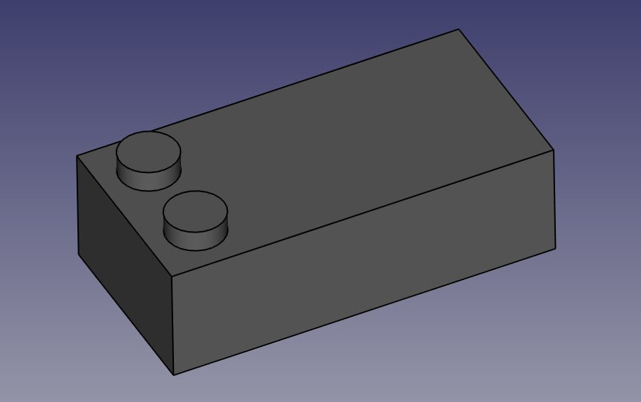
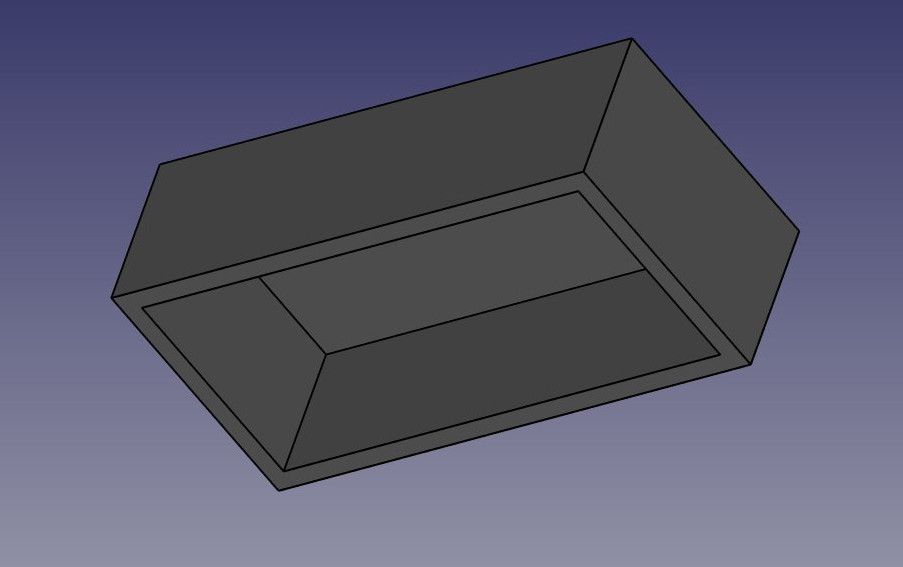
To illustrate how the PartDesign Workbench works, let's model this well-known piece of Lego:
The cool thing with Lego pieces is that the dimensions are easy to obtain on the Internet, at least for the standard pieces. These are pretty easy to model and print on a 3D printer, and with a bit of patience (3D printing often requires much adjustment and fine-tuning) you can make pieces that are totally compatible and click perfectly into original Lego blocks. In the example below, we will make a piece that is 1.5 times bigger than the original.
We will now use exclusively the Sketcher and PartDesign tools. Since all the tools from the Sketcher Workbench are also included in the Part Design Workbench, we can stay in Part Design and we will not need to switch back and forth between the two.
Part Design objects are fully based on Sketches. A Sketch is a 2D object, made of linear segments (lines, arcs of circle or ellipses) and constraints. These constraints can be applied either on linear segments or on their endpoints or center points, and will force the geometry to adopt certain rules. For example, you can place a vertical constraint on a line segment to force it to stay vertical, or a position (lock) constraint on an endpoint to prohibit it to move. When a sketch has an exact amount of constraints that prohibits any point of the sketch to be moved anymore, we talk about a fully constrained sketch. When there are redundant constraints, that could be removed without allowing the geometry to be moved, it is called over-constrained. This should be avoided, and 3D-CAD-X will notify you if such a case occurs.
Sketches have an edit mode, where their geometry and constraints can be changed. When you are done with editing, and leave edit mode, sketches behave like any other 3D-CAD-X object, and can be used as building blocks for all the Part Design tools, but also in other workbenches, such as Part or Arch. The Draft workbench also has a tool that converts Draft objects to Sketches, and vice-versa.
Let's start by modeling a cubic shape that will be the base of our Lego brick. Later on we will carve the insides, and add the 8 dots on top of it. So let's start this by making a rectangular sketch that we will then extrude:
Switch to the PartDesign Workbench
Click on the Sketcher  New Sketch button. A dialog will appear asking where you want to lie the sketch, choose the XY plane, which is the "ground" plane. The sketch will be created and will immediately be switched to edit mode, and the view will be rotated to look at your sketch orthogonally.
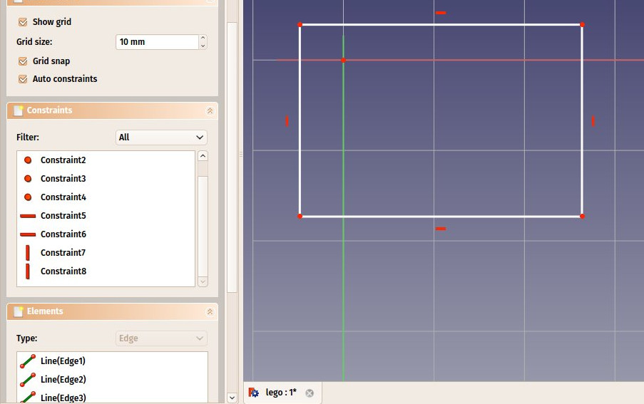
Now we can draw a rectangle, by selecting the Sketcher  Rectangle tool and clicking 2 corner points. You can place the two points anywhere, since their correct location will be set in the next step.
You will notice that a couple of constraints have automatically been added to our rectangle: the vertical segments have received a vertical constraint, the horizontal ones a horizontal constraint, and each corner a point-on-point constraint that glues the segments together. You can experiment moving the rectangle around by dragging its lines with the mouse, all the geometry will keep obeying the constraints.
Now, let's add three more constraints:
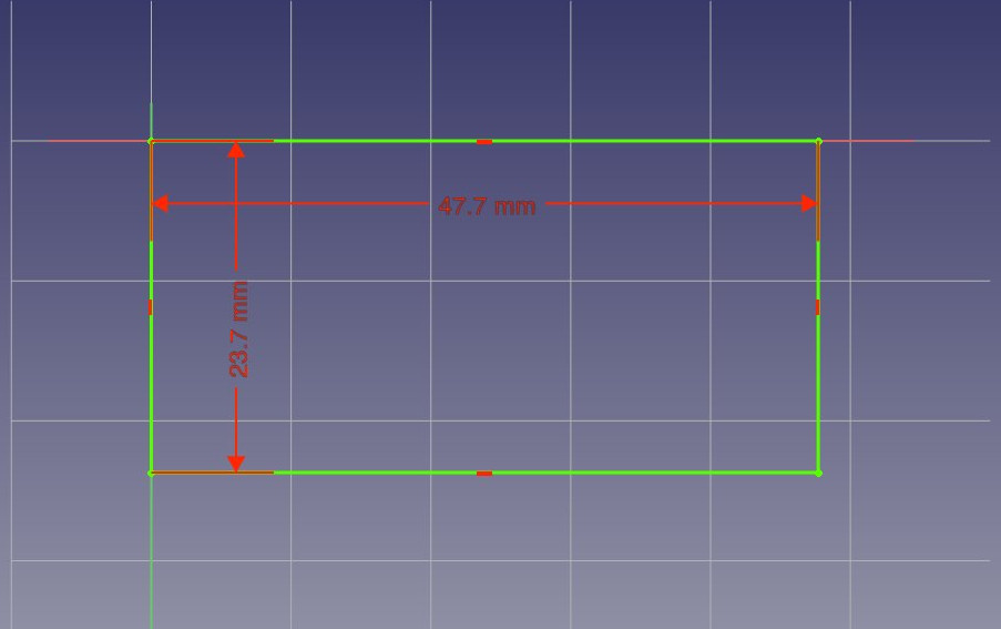
Select one of the vertical segments and add a  Vertical Distance Constraint. Give it a size of 23.7mm
Select one of the horizontal segments and add a  Horizontal Distance Constraint. Make it 47.7mm.
Finally, select one of the corner points, then the origin point (which is the dot at the crossing of the red and green axes), then add a  Coincident Constraint. The rectangle will then jump to the origin point, and your sketch will turn green, meaning it is now fully constrained. You can try moving its lines or points, nothing will move anymore
Note that the last point-on-point constraint was not absolutely necessary. You are never forced to work with fully constrained sketches. However, if we are going to print this block in 3D, it will be necessary to maintain our piece close to the origin point (which will be the center of the space where the printer head can move). By adding that constraint we are making sure that our piece will always stay "anchored" to that origin point.
Our base sketch is now ready, we can leave edit mode by pressing the Close button on top of its task panel, or simply by pressing the Escape key. If needed later on, we can reenter edit mode anytime by double-clicking the sketch in the tree view.
Let's extrude it by using the  Pad tool, and giving it a distance of 14.4mm. The other options can be left at their default values:
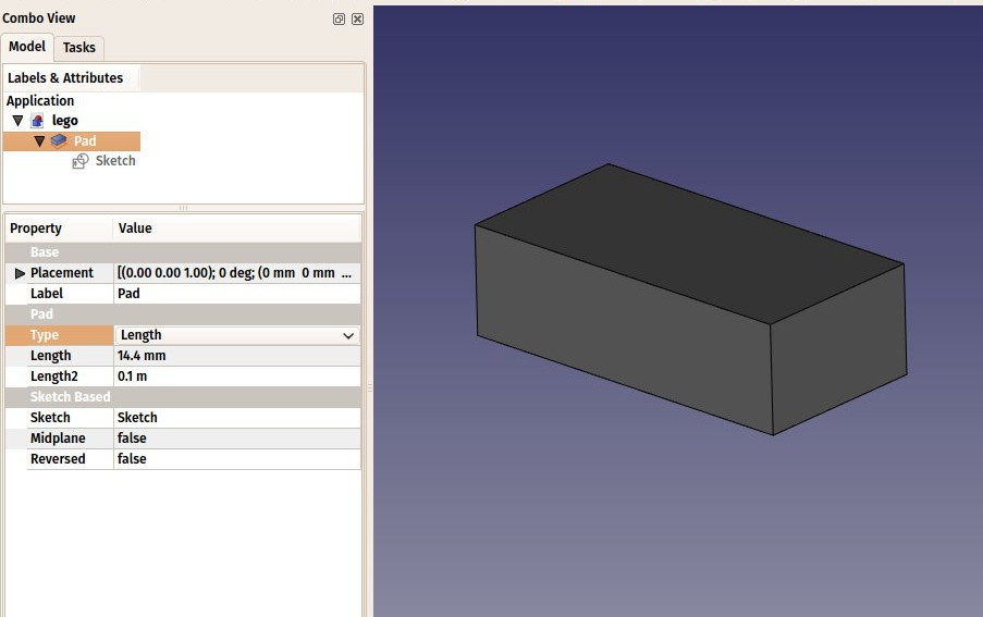
The Pad behaves very much like the Extrude tool that we used in the previous chapter. There are a couple of differences, though, the main one being that a pad cannot be moved. It is attached forever to its sketch. If you want to change the position of the pad, you must move the base sketch. In the current context, where we want to be sure nothing will move out of position, this is an additional security.
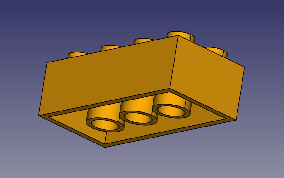
We will now carve the inside of the block, using the  Pocket tool, which is the PartDesign version of Part Cut. To make a pocket, we will create a sketch on the bottom face of our block, which will be used to remove a part of the block.
With the bottom face selected, press the .svg) New sketch button.
New sketch button.
Draw a rectangle on the face.
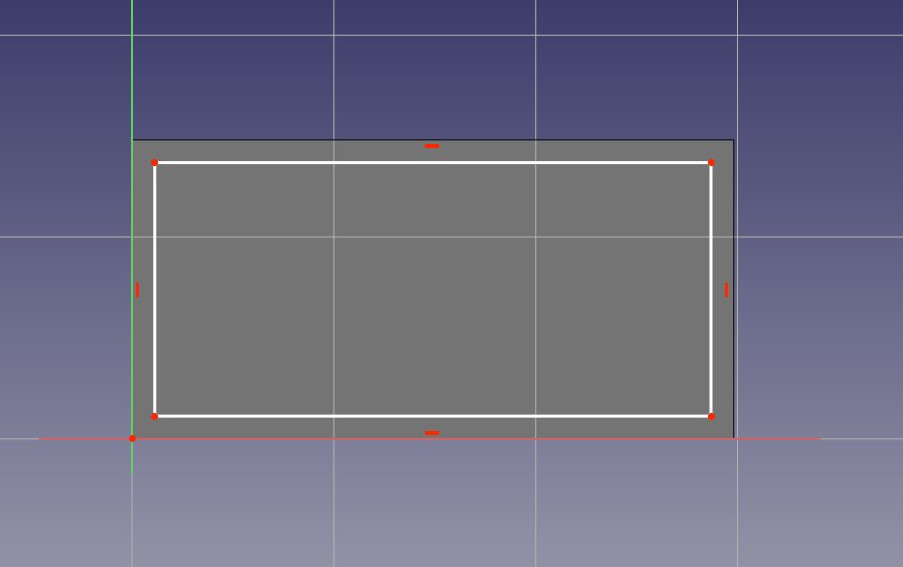
We will now constrain the rectangle in relation to the bottom face. To do this, we need to "import" some edges of the face with the  External geometry tool. Use this tool on the two vertical lines of the bottom face:
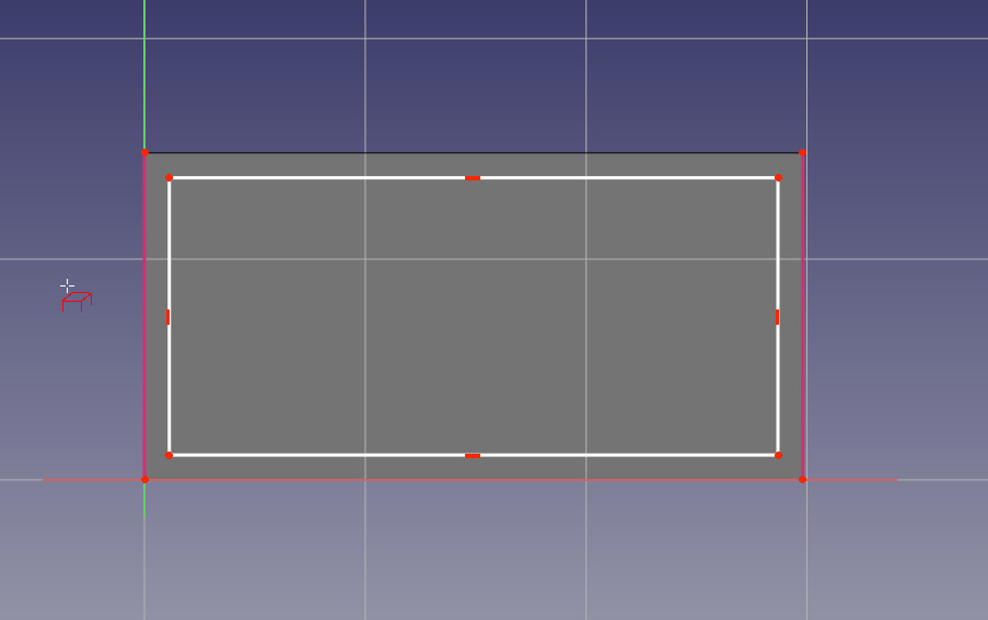
You will notice that only edges from the base face can be added by this tool. When you create a sketch with a face selected, a relation is created between that face and the sketch, which is important for further operations. You can always remap a sketch to another face later with the  Map sketch tool.
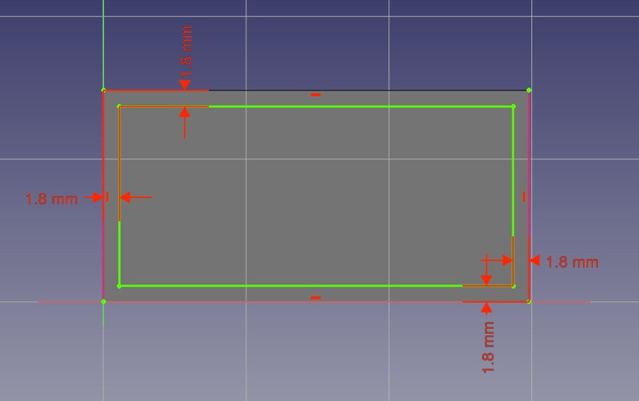
The external geometry is not "real", it will be hidden when we leave edit mode. But we can use it to place constraints. Place the 4 following constraints:
1. Select the top left point of the rectangle and the top point of the imported line and add a Horizontal Distance Constraint of 1.8mm
2. Select again the top left point of the rectangle and the top point of the imported line and add a Vertical Distance Constraint of 1.8mm
3. Select the bottom right point of the rectangle and the bottom point of the right imported line and add a Horizontal Distance Constraint of 1.8mm
4. Select again the bottom right point of the rectangle and the bottom point of the right imported line and add a Vertical Distance Constraint of 1.8mm
Leave edit mode and we can now perform the pocket operation: With the sketch selected, press the Pocket button. Give it a length of 12.6mm, which will leave the upper face of our pad with a thickness of 1.8mm (remember, the total height of our pad was 14.4mm).
We will now attack the 8 dots on the top face. To do this, since they are a repetition of a same feature, we will use the handy  Linear pattern tool of the Part Design Workbench, which allows to model once and repeat the shape.
Start by selecting the top face of our block
Create a New sketch.
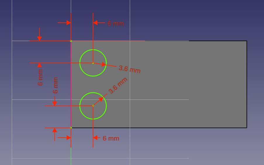
Create two  circles.
For each circle, select it and add a  Radius Constraint of 3.6mm to each of them
Import the left edge of the base face with the External geometry tool.
Place two vertical constraints and two horizontal constraints of 6mm between the center point of each circle and the corner points of the imported edge, so each circle has its center at 6mm from the border of the face:
Notice how, once again, when you lock the position and dimension of everything in your sketch, it becomes fully constrained. This always keeps you on the safe side. You could change the first sketch now, everything we did afterwards would keep tight.
Leave edit mode, select this new sketch, and create a Pad of 2.7mm: